A while ago, I saw a video by Ben Eater “So how does a PS/2 keyboard interface work?” (Odysee, YouTube). After this video I’ve been reading up on the PS/2 interface. I’ve looked at this before, made a break out board for a dual PS/2 connector. As the PS/2 interface is an open collector, it needs pull up resistors to the 5 Volt rail. So, I created a break-out board, with pull up resistors in place. But I goofed up, and swapped the VCC and GND. Maybe I looked at the plug pinout in stead of the socket pinout? Anyhow, I goofed up, put the boards and sockets in some drawer and moved on. Now, I saw that video, and decided to give it another try. The solution is simple, mount the connector on the other side of the board.
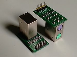
PS/2 Break Out Flip
So… let’s see… what is the signal I am trying to decode. So, the clock and the data line are idle high. Then the clock starts ticking, on the falling edge, I capture the data line. I capture 11 bits, these are, start bit, 8 data bits, 1 parity bit, and 1 stop bit. The clock for this is between 10.0–16.7 kHz. Looking at the signal specs, it might be decodable if I feed it into an UART (at appropriate levels, obviously). I’ve seen references to this in the Linux kernel, so it should work.
One thing to be aware of, I am pulling the clock and data lines up to 5 Volts. If we want to connect a microcontroller, we need to make sure it can handle such high I/O voltages. Luckily STM32 microcontrollers are 5 Volt Tolerant on most pins. Make sure the I/O pins you use are 5 Volt Tolerant.
Now, let’s see if we can communicate with it. First, I will define the communications format. As described before, we have 1 start bit, 8 data bits, 1 parity bit and 1 stop bit. To define such in C, I will use unsigned int variable : 1;, where the : 1 specifies the length of the bitfield. I place multiple of those in a struct to create the frame we desire. Then, I place the resulting struct in a union with an int such that I can fill it bit by bit. Be aware, for this to work like I describe here, we must run the code on a Little Endian architecture. However, these days Big Endian architectures are rare.
typedef struct {
  union {
    struct {
      unsigned int start : 1;
      unsigned int data : 8;
      unsigned int parity : 1;
      unsigned int stop : 1;
    };
    int raw;
  };
} ps2_frame_t;
As an initial test, I will read the keyboard using GPIO. I will wait for the clock line to go low, read one bit, wait for the clock line to go high, and repeat until I have received 11 bits. By no way this is a real implementation as I spend all my time busy waiting, and thus cannot do anything else. This is mostly a test to verify my setup.
int count; ps2_frame_t ps2_frame;
while (1) {
  if (count == 0) ps2_frame.raw = 0;

  while (ReadPin(PS2_CLOCK));
  ps2_frame.raw |= ReadPin(PS2_DATA) << count;
  count++;
  while (!ReadPin(PS2_CLOCK));

  if (count == 11) {
    count = 0;
    print_hex(ps2_frame.data);
  }
}
And sure enough, the code above presents the scan codes we are expecting to see. So, time to think about a real implementation. For this, I have set up an interrupt on the falling egde of the clock. When this interrupt is trigered, I read the data line again. There is no busy waiting involved, and the microcontroller can be doing other things when the keyboard is inactive.
volatile bool data_ready = false;
volatile uint8_t data = 0;
void on_clock_falling_egde_interrupt(void) {
  static ps2_frame_t ps2_frame;
  static int count = 0;
  ps2_frame.raw |= ReadPin(PS2_DATA) << count;
  count++;
  if (count == 11) {
    count = 0;
    data = ps2_frame.data;
    ps2_frame.raw = 0;
    data_ready = true;
  }
}

void main_loop(void) {
  do_something_else();
  if (data_ready) {
    data_ready = false;
    print_hex(data);
  }
}
This should work, however, after pressing a few keys, it seems I lost synchronisation. It lost track of where my frame starts. Why does this occur? In order to debug such event, I decided to toggle a pin when I enter my interrupt handler, such that I can look at my logic analyser to see when I am in the interrupt reading the data pin. D0 = Clock, D1 = Data, D2 = Microcontroller in interrupt
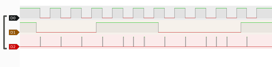
From this is seems we are some times receiving an interrupt at the rising edge as well. Throwing us out of sync. Why this might occur? I could imagine the falling edge being too slow. I am only looking at a logical analyser, so I have no view of the analogue values. Anyhow, adding a check whether the data line is actually low fixes this issue.
Where to expand from this? I am thinking about adding a timer, this way I can ensure transitions are happening at times they should. Furthermore, this enables me to add a timeout and reset the state in case of errors. Furthermore, I would like to implement controller to device communication. One thing this would allow me to do is controlling the LEDs on the keyboard, and it would allow me to support mice as well.
Resources:
https://en.wikipedia.org/wiki/PS/2_port
https://allpinouts.org/pinouts/connectors/input_device/mouse-keyboard-ps-2/
https://valhalla.altium.com/Learning-Guides/PS2-PS2_Controller.pdf
https://wiki.osdev.org/PS/2_Keyboard
https://wiki.osdev.org/PS/2_Mouse
https://www.avrfreaks.net/sites/default/files/PS2%20Keyboard.pdf
https://download.microsoft.com/download/1/6/1/161ba512-40e2-4cc9-843a-923143f3456c/translate.pdf
https://www.vetra.com/scancodes.html
https://www.win.tue.nl/~aeb/linux/kbd/scancodes-12.html
https://www.win.tue.nl/~aeb/linux/kbd/scancodes-13.html