Back in 2019 I bought my KGSER Soldering station. I have been happy with this soldering station. Recently I’ve decided to buy two more of them? Why? I wish to test an open source replacement firmware, while keeping the original. Then, why two of them? From what I read on there, it appears to be possible to convert them to accept JBC tips in stead of Hakko tips. As such requires a hardware modification, I would like to try this with another unit.
The unit I bought back in 2019 is a version 2 unit (2.1S to be precise), and I’ve decided to buy to more version 2 units. They seem cheaper then the version 3 units, and I don’t see the justification for the price difference. The alternative firmware can be built for both anyways, so it seems logical to stick with revision 2, as I am already familiar with this unit.
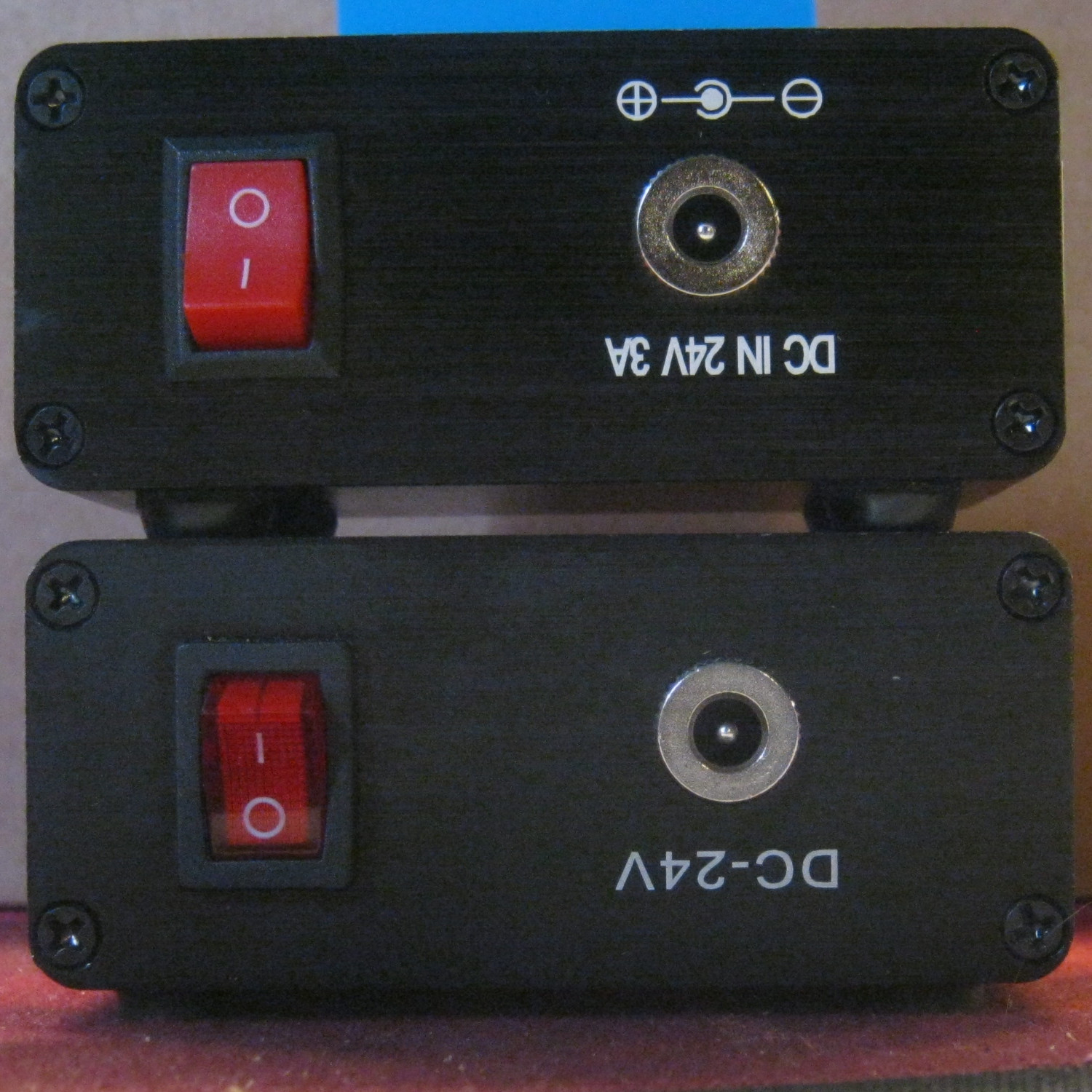
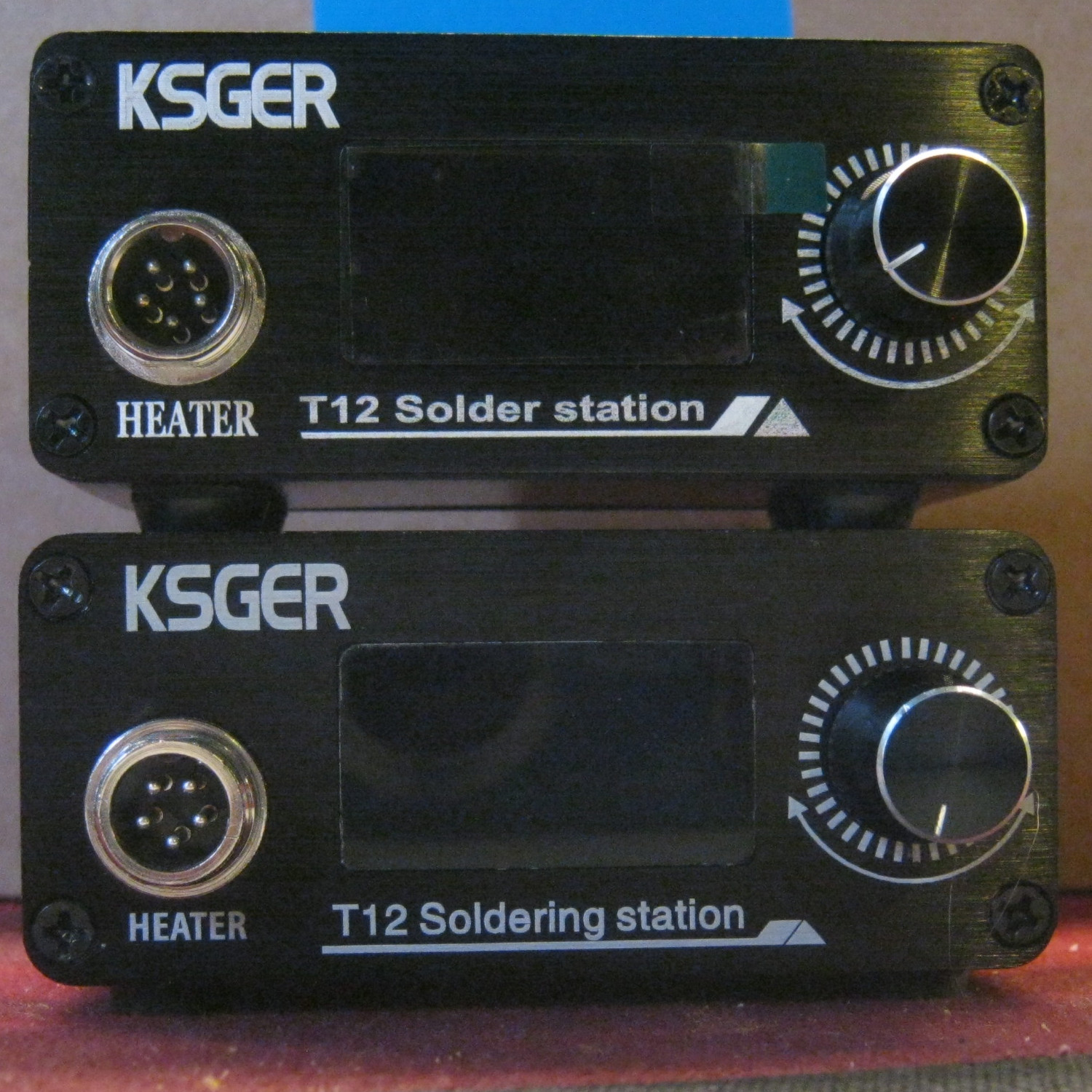
First, let’s look at them. On the front, we see they have changed the fonts a little. But other then that, it seems pretty similar. On the back, however, we see they have used a different power switch. The power switch in the 2019 model has a light in it, and at runs pretty hot during operation. My best guess is the light they’re using isn’t rated for 24 volts. It seems they’ve addressed that problem. However, now the top position is the off, while it was the bottom position in the older revision. Another thing to note, the writings are still upside-down, but now they’ve added a polarity symbol, and a current rating.
Turning the unit on reveils the old unit runs firmware revision 2.10 while the new units run 2.12. As these are readback protected, I cannot create a backup of them. Okay, I am aware the readback protection on STM32F1xx has been hacked, but really, why bother, there are backups online, at least, for the 2.12 version. (Should I bother to attempt to backup the 2.10 version?) The 2.12 firmware still has the issue that it takes several seconds for something to appear on the display. It’s a minor issue, yet, back in 2019, first time turning it on, I was like, after a few seconds, this ain’t working, and switching the power off again. Now I know I have to wait.
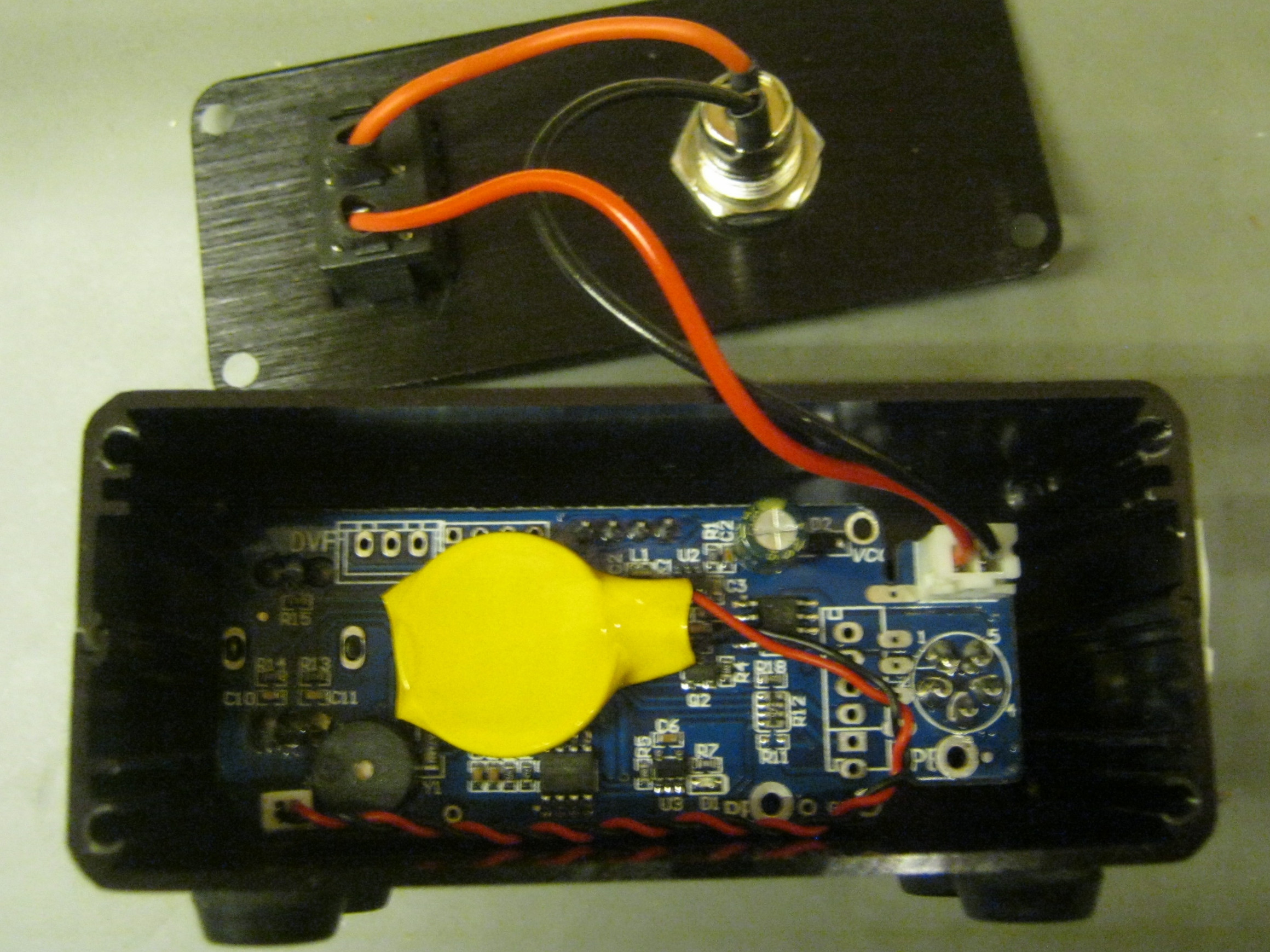
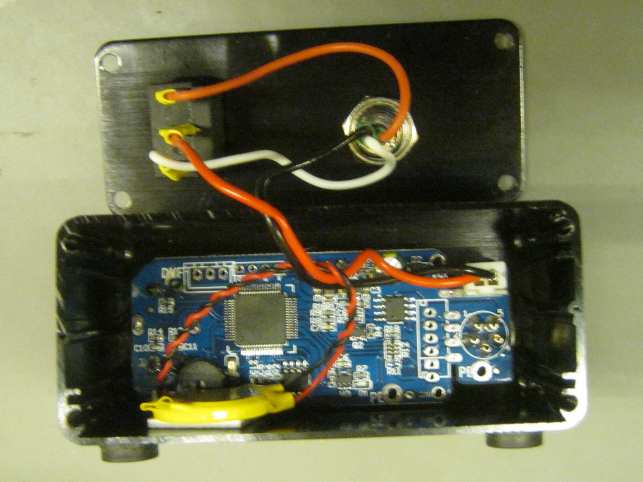
A look inside, from first glance, it looks like the same PCB. They’ve mounted the RTC battery differently, but there is little more to say. Having the backs off, I could mount them back such that the text ain’t upside-down. The switch on the new one would be correct now, so I should flip the switch on the old one if I switch the back plane. Sounds simple enough. But it turned out that switch is a bitch to get out. So that’ll have to wait for later. I was already wondering why I hadn’t flipped the back earlier.
Well… after all of this, I guess it’s time to continue. But before I start flashing the new firmwares, I guess I should give them a test run on stock firmware. It’s untested hardware after all, and before I blame the new firmware being faulty, I guess I should verify the hardware works on stock firmware in the first place.
As this article is getting long, even before I started testing anything, I will end this article here, stay tuned for part 2.