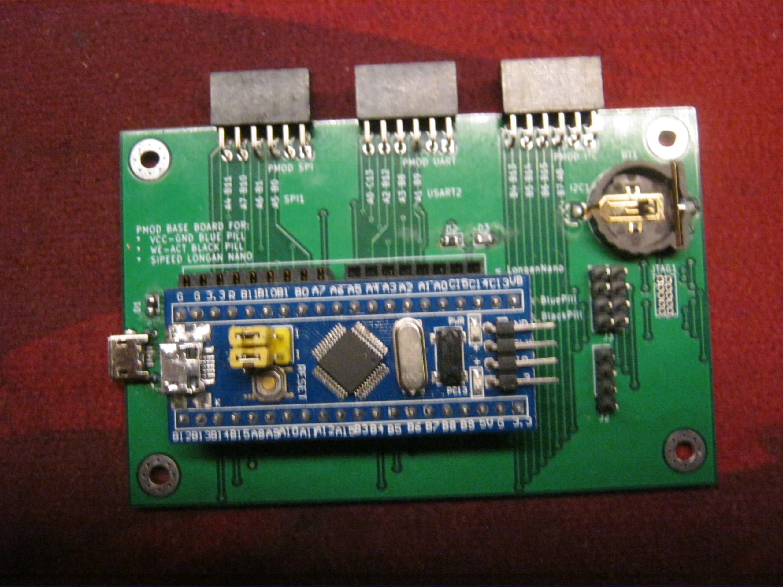
I’ve been working on some base board that can hold a Blue Pill, Black Pill and a Longan Nano. These boards have similar pinouts, like just one pin off. This base board will lead to Pmod connectors. The plan is to 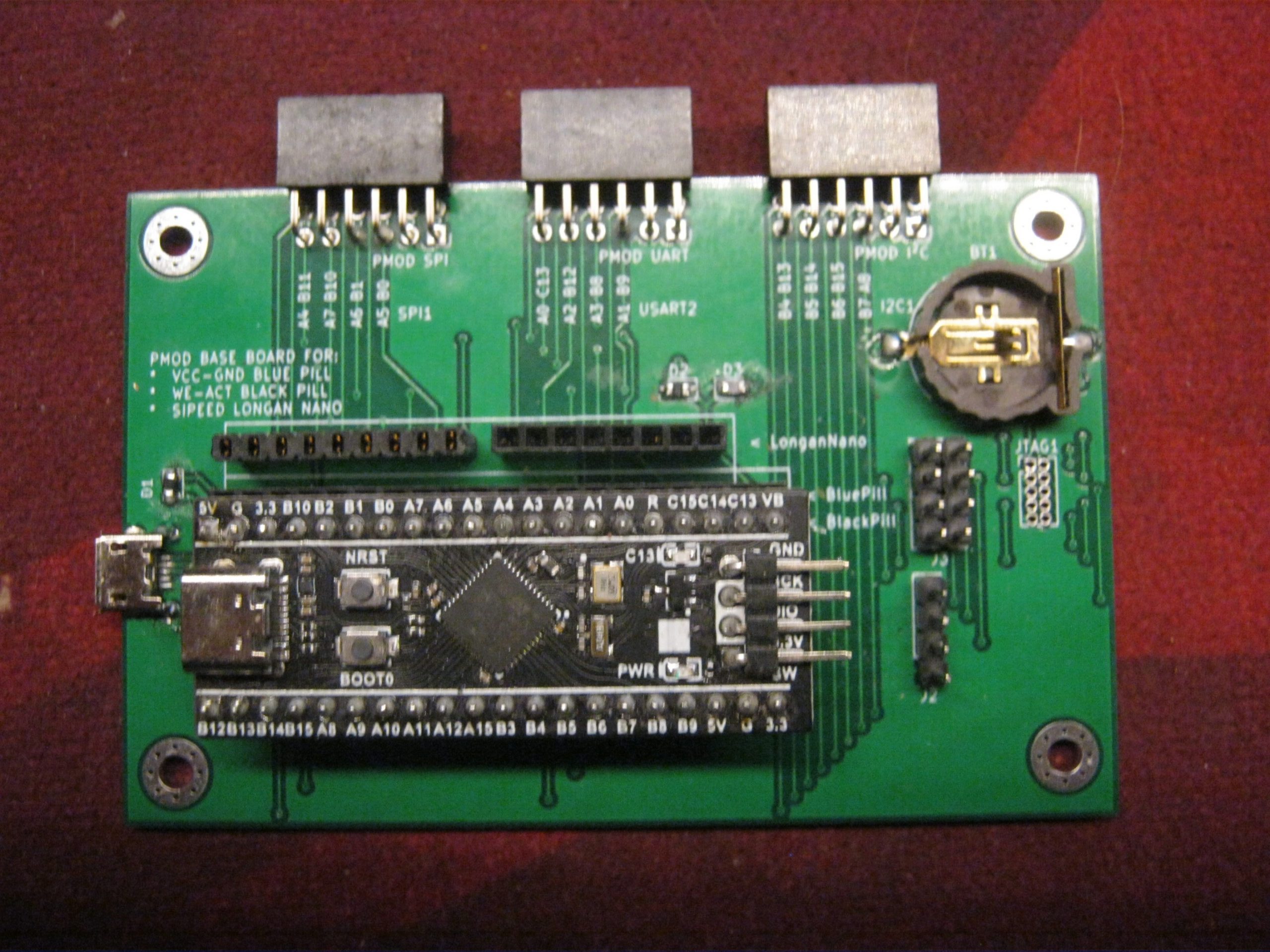
create some adapter baords for various modules that go on eBay/AliExpress, for ease of connection. As I tried to give an (online) course on electronics and microcontrollers last summer. Wiring things up turned out to be a little of a hassle when one begins with it all. Therefore, something that you just plug in and it is connected as designed 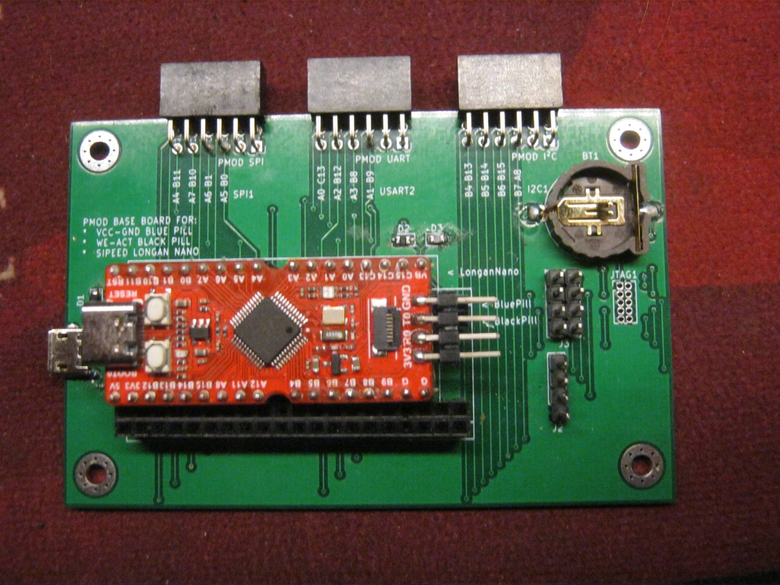
seems nice. As my first prototypes came in, I realised I made some design issues with the debug header being to close, and I decided to move the USB port for convenience such that the header won’t be in the way when reworking.
One of the other parts to come in play are sub-ghz radio chips. For this case, I will look at a Si4332, a popular module on AliExpress, even though the manufacturer does not recommend it for new designs. Nevertheless…. it’s cheap! This board is offered in 433, 470, 868 and 915 MHz versions. As I live in Europe, the 433 and 868 Mhz ones are in the bands I can legally use. Therefore I ordered two of each. Note the board they send looks the same, but comes with a different antenna. Let’s hope they also mounted different tuning parts. You never know with stuff from China. Oh well…
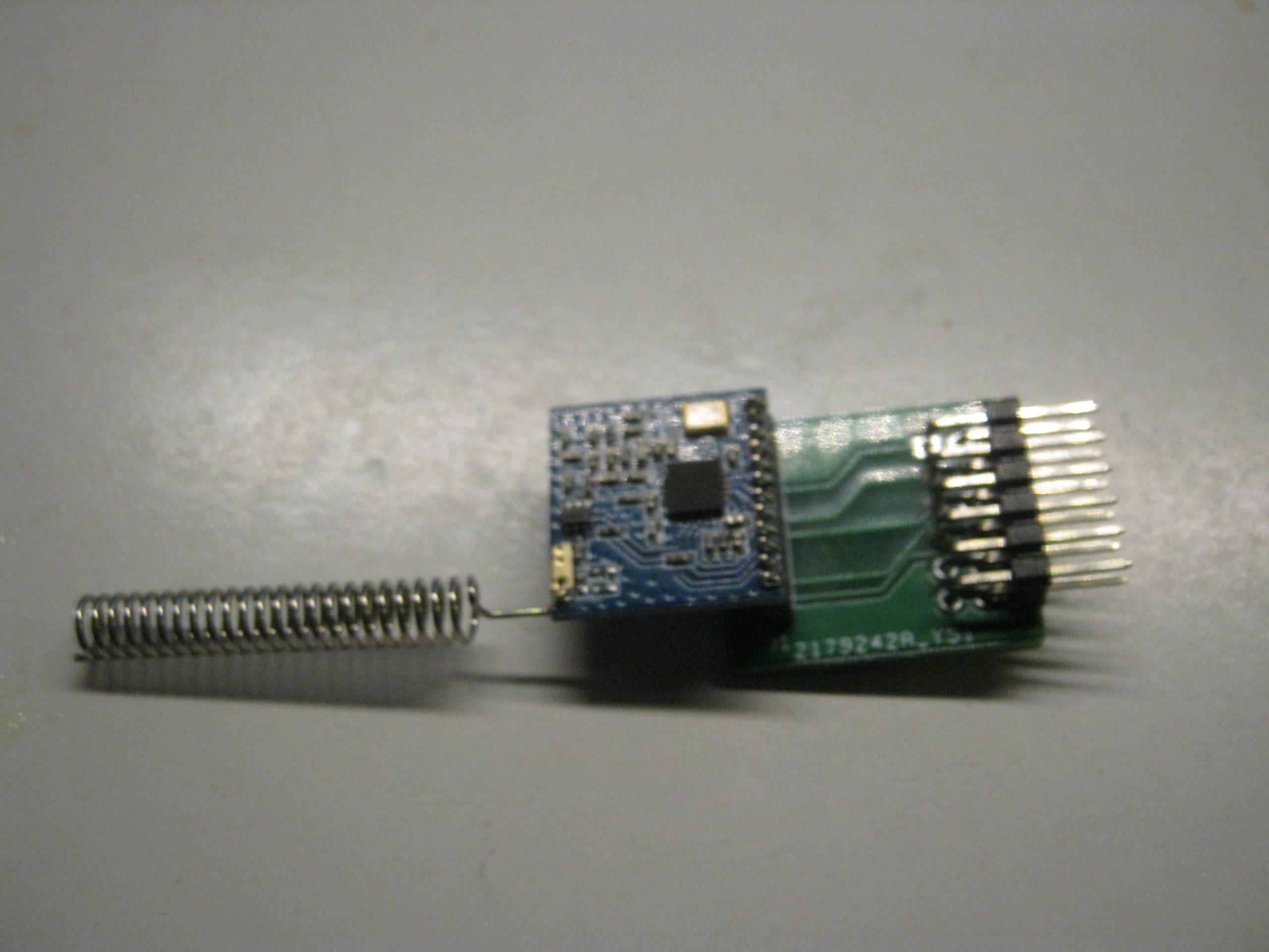 Now, we are looking at modules with holes at a 1.27 mm pitch. So it’s not just slapping a header on there and put it in a breadboard. I’ll need some adapter board for that. As I was working on the PMod stuff, I figured I’d make an adapter to PMod for the stuff. However, I goofed up the pinout on that breakout.
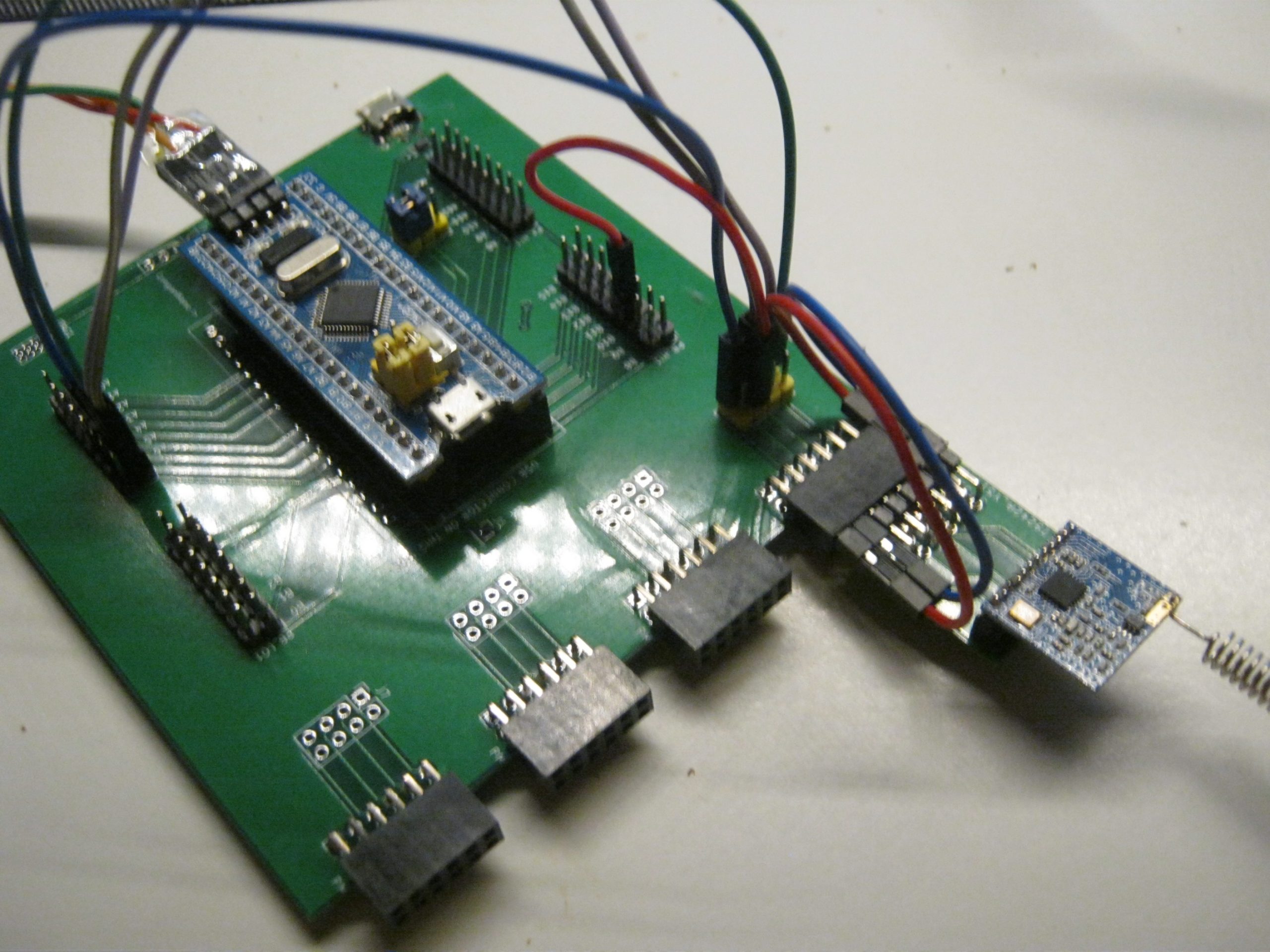 I have created a second board, for the user to do the wiring, in stead of the fixed wiring of the above, with extended PMod SPI, UART and I²C pinouts. And with such a board I was able to communicate with the module. I have tested the communication by requesting the chips identifier, which matched the expected values. I have not tested any radio capabilities yet. I am thinking how to continue from here. I might look at Jan Gromeš‘s RadioLib and Unduino that code. As I like to have a C library rather then C++ running on top of Arduino. Wether I will port the whole thing, or just use it as a reference is not decided yet. RadioLib’s license is MIT, and so is the code I wish to release, so from that point of view it is compatible.
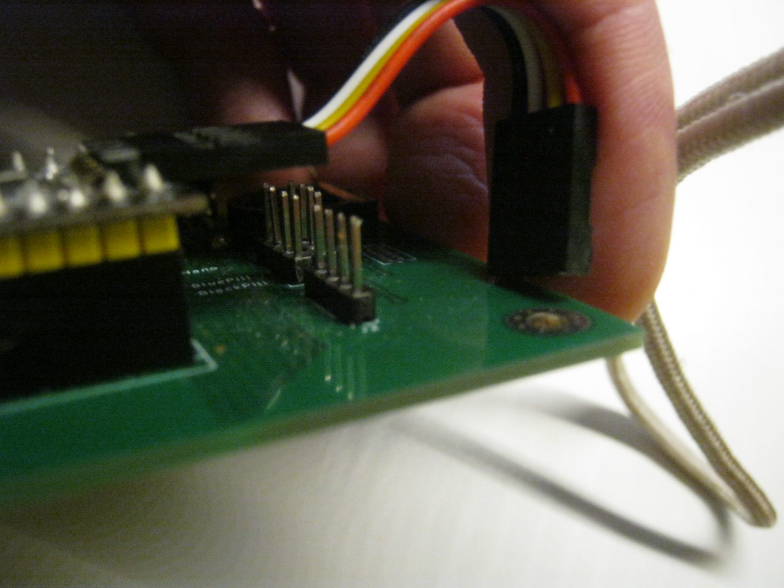 But that’s for later concern. First of all… I am working on updating the boards. The little breakout where I goofed up the pinout, but also for the base boards there are some issues to resolve, such as the debug pins being too close to connect, and it seems I have left out the UART header I had planned. So some things to be added. And next, is the I²C board to connect various eBay/AliExpress modules. The planning was to do some I²C stuff first, before doing SPI stuff. And while this radio thing is SPI, I’m not sure yet wether I am putting it in the upcoming SPI board, or leave it as a small breakout is it is now.
But all of that for later, let’s first get the I²C board schematic finished, routed, and produced. Then we can see how it works, and see if I might give another course, this time, without the part where we wire the breadboard, as it seems this was an error-prone part for an online course.