Pine64 introduced the Ox64 recently. This board features a Bouffalo Lab BL808 MCU. Inside this MCU we’ve got 3 different cores. The core referred to as M0 is an RV32IMAFCP T-Head E907 core. The core referred to as D0 is an RV64IMAFCV T-Head C906 core, finally there is a core referred to as LP, which is an RV32EMC T-Head E902 core. In this chip we’ve got 64 MiB of RAM. The flash is external, and in case of my board, 16 MiB. There is also a 2MiB version, but I went for the largest option.
Now, a RV64IMAFCV core, that sounds like something that can run Linux. Let’s have a look. On the Bouffalo Lab github, there is a repo bl808_linux. This codebase appears to only compile with the gcc version they’ve linked in their documentation. It seems they use some extension that doesn’t exist or isn’t enabled in the gcc version for RISCV in the Arch Linux repo. But for now, let’s go ahead and use their version of gcc.
After building and flashing, I ran into a problem. That repo was made with a different board in mind. The pins they’re using for UART are not connected to pins on the Ox64 board. Patching it to different pins ain’t trivial as the code looks like:
		writel(0x00401502, (void *)0x200008e4); //IO8, TXD
		writel(0x00401517, (void *)0x200008d8); //IO5, RXD
The reference manual ain’t that useful, it seems not all registers are documented. I’ll have to go through the source code in the bl_mcu_sdk repo. If I were to do this, I would make a fork on github where I do my changes. Now, if anyone else would do this, they’d do the same, right? Now, there are 14 forks, so I went looking through them, and one of them had the UART patches in there: A fork by Zagitta. So, let’s go ahead with that fork. Building, uploading, and we’re booting.

So, how to build Linux and flash the Ox64? Let’s go!
To flash the board, we need to download “Bouffalo Lab Dev Cube” from https://dev.bouffalolab.com/download. Note that this is a GUI application, so flashing cannot be automated using this tool. There exist some console flasher for Bouffalo Lab chips, but this will need some more investigation.
Now, the said GUI tool is a bit iffy. It doesn’t seem to like my multi monitor setup much,
The pinout for the fork I am using, uses GPIO16 and GPIO17 for the Linux UART. These pins aren’t even marked as being UART pins on the official pinout.
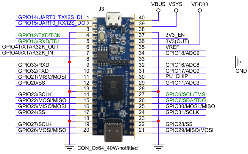
| 1 (GPIO14) | Programming Uart TX | |
| 2 (GPIO15) | Programming Uart RX | |
| 30 (PU_CHIP) | Reset Line | |
| 31 (GPIO17) | Linux Uart RX | |
| 32 (GPIO16) | Linux Uart TX |
Put a breadboard wire on pin 30. This is the reset pin.
Start the Bouffalo Lab Dev Cube application. Please note, one might wish to disable secondary monitors, as my multi-monitor setup confuses the application. While the executable is called BLDevCube-ubuntu, it works fine on other distros, at least, it works on Arch.
Enter the “MCU” tab, Set “M0” to “group0”, set “D0” to “group1”, set the “Image Address” for both to “0x58000000”, browse to the build output directory where you compiled your code, and select “low_load_bl808_m0.bin” and “low_load_bl808_d0.bin” respectively.
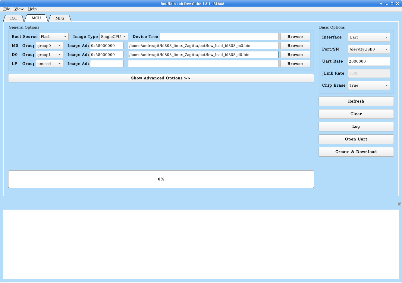
Now, press the boot button on the board, and tap the USB connector with the breadboard wire to enter bootloader mode. Then click the “Create & Download” button.
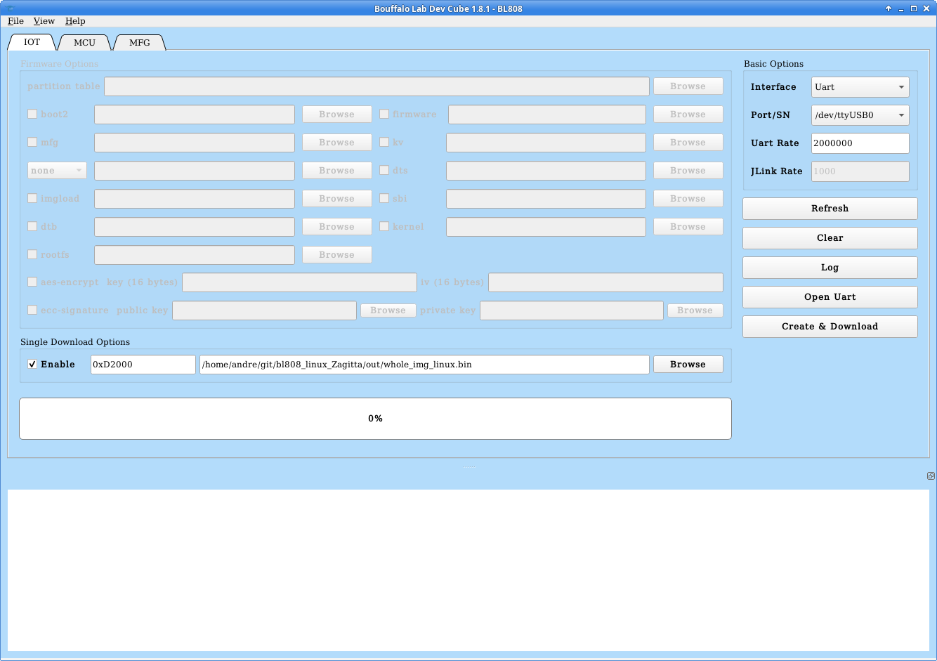
After the flashing is complete, go to the “IOT” tab, and make sure “Enable” is elected at the “Single Download Options”, set the address to 0xD2000, then select the “whole_img_linux.bin” from the compilation output. Finally, click the “Create & Download” button again.
If you run into errors: Make sure you have entered bootloader mode, by using the breadboard wire to reset the MCU while holding the button on the board. Pressing the button while powering the board up is not sufficient. Furthermore, make sure nothing is connected to the JTAG pins (4,5,26,27). As the GPIO12/GPIO13, Pin 4,5, are marked UART on the schematic, I had an UART on there, which made flashing fail. Having a CKLINK debugger probe on there does not prevent the flashing to work.
Once flashing is done, have an UART bridge at GPIO16 and GPIO17, at 200Kbps, and you reset the board again. Then it should show the board booting Linux.
We now have the board booting, but it ain’t doing much useful yet. Next steps is seeing whether it is possible to get the RF (µSD) slot working. This probably would require writing drivers, looking at this github issue. In the Reference Manual is no documentation regarding SD at all. There is code in the bl_mcu_sdk repo… Oh well…
While I got Linux booting, at the moment it seems to be too incomplete to be usable. Furthermore, I have questions. How does it boot? What are these low_load files? Obviously it is one file for the “M0” core and one file for the “D0” core, but as I gave them both address “0x58000000”, how does that work? Is there some memory mapping going on from addresses on each core’s busses to the actual address in flash? It must be something like that. I’ve found these notes about the boot process. Some answers regarding the mapping procedure might be found in this article about the BL602.
Nice article. What pins do you use to flash the linux image to the chip? Or can that be done via USB?
Is there maybe a UART converter on the Ox64, so both flashing and interacting with Linux could be done via USB?
The table I have in my post lists “Programming UART”. These pins are used.
The micro-usb connector is power only, the usb-c connector is connected to the native USB pins of the microcontroller. There is no UART bridge present.
It might be possible to remap the RV64 core UART output to same pins as the programming pins. However… that means the RV32 core has to be removed from those pins, since they output some lines when the device is powered up. The boot process of this chip isn’t entirely clear to me yet. Do the three cores power up independently or is one in control of the other?
Today I found this YouTube video
https://www.youtube.com/watch?v=czRtF-UNiEY
It looks like they’ve got SD card support in. I might have another look at those boards.