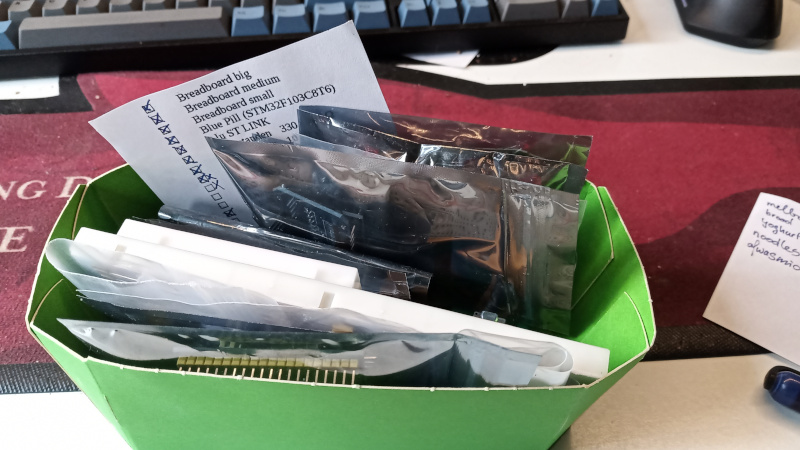
 Well everyone, it has been a while. What have I been up to? Earlier this year I have been teaching some basics about embedded to friends and colleagues. A blue pill, a breadboard, a bag of wires, and some peripherals. There we go.So this went on for a couple of weeks till I discussed all the parts I supplied. Then it was my vacation, which I spend at home due a pandemic. I would have been at a festival if it wasn’t for that nasty virus having a grip on the world.
But what have I been up to. I’ve been playing around with some I²C and SPI peripherals from aliebay. Tried to hook up all the I²C devices I could find and make them work. Temperature sensors, humidity sensors, barometers, ambient light sensors, etc. For now the most basic examples, as in, make the sensor read some value. I haven’t been into tuning the configuration, just use the defaults, or write the most basic setting, to make it work. See https://github.com/a-v-s/ucdev/tree/master/demos/i2c for the code.
Looking around at aliebay. One of the things I’ve noticed, they’ve started selling Blue Pills with a STM32F103C6T6 in stead of the usual STM32F103C8T6. Please be aware of this. While the 6 in stead of the 8 indicated 32 KiB of Flash in stead of the 64 KiB, which actually contains 128 KiB, as the C8 and CB are the same silicon die (410), the C6 is different die (412) (die list). This is a thing to be aware of, it’s not simply the same chip with less flash and ram, it’s actually different silicon, which has less peripherals. For example, the STM32F103C8 has two SPI interfaces, while the STM32F103C6 only has one SPI interface. I have purchased one such Blue Pill, but I haven’t used it as of yet. Therefore, these notes are only from the documentation, not from practice.
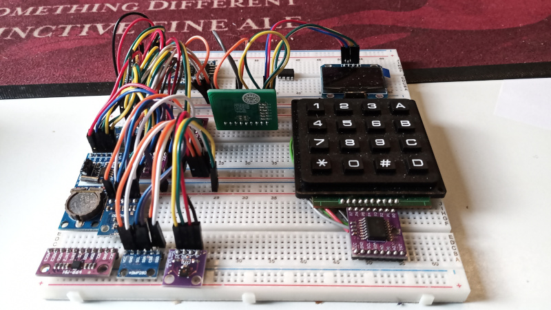 A few observations. All I²C sensors I’ve seen so far, when offering data in a size greater then 1 byte, use the Big Endian format. Furthermore, most sensors use a traditional register interface. Some use a command instead of a register. A traditional register interface makes sense if it were based on a simple architecture, like 8051. Such architecture is an 8 bit architecture, and therefore has no native Endianess. However, the compiler does. I believe Keil is, or at least was, a popular compiler for the 8051 target. The Keil compiler happens to use the Big Endian format when using integers greater then 8 bit. On the other hand, the SDCC compiler, which also can target the 8051 architecture, uses Little Endian. But hey, this is only speculation, and I an getting off. One sensor in particular, a Bosch BM-280, a barometer, has some on board storage that contains calibration values. These values, on the other hand, are stored as Little Endian. Be aware of that, the sensor data is Big Endian, but the calibration data is Little Endian.
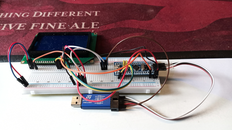
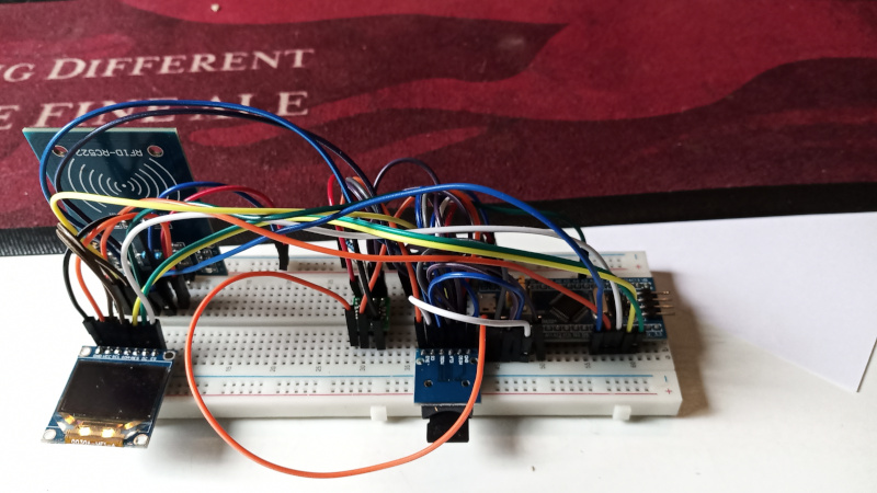 I’ve also been playing around with the SPI bus. On here, I’ve been looking at SPI Flash, SD cards, and displays. I’ve also gotten the MFRC522 RFID card reader on there. I’ve got my transport layer so I can also use I²C to read cards, on the I²C board. (RobotDyn sells I²C capable boards, most others are hard wired so SPI) One of the displays I have had laying around was a PCD8544. These are usually marketed as “Nokia 5110 display”. Oh… Nokia is still a legend, right? I was only getting garbage on the screen. I’m not sure what is wrong there… but I suspect this unit is broken. I’ve ordered some more to test. The other display is a ST7920. This one works, so I have reason to believe my set-up is correct. What I did was make an interfacing layer between u8g2lib from olikraus and my ucdev.
 There is another observation of the ST7920. This unit seems to respond to data on the SPI bus even when it’s chip select line is not asserted. This means simply sharing the bus won’t work. I might have to play around with some AND gates to make it play nice with other devices on the bus. I’ve ordered some logic chips for this purpose.
But then, my beadboards are full of wire spaghetti. And swapping the Blue Pill for a Black Pill requires rewriting. That’s why I decided to work on an adapter board. Taking a Blue and a Black Pill. The pins are only shifted one pin on one side, and taking note of the pin that’s 5 Volt on the Black Pill and GND on the Blue Pill. When I was at it, I also drew a Longan Nano in there. So that is step one, having sockets where the different boards go into. But then… what’s next?
When I wish to interface, I have come across two standards, UEXT from Olimex and Pmod from Digilent, which I decided to draw in. But before I get there… I need to decide how I wish to wire things up. I might have a lot of jumpers on there, to expose as much as possible of the functionality the Blue and Black Pills offer. This is still a work in progress… What I have so far is at https://github.com/a-v-s/ucdevboard.