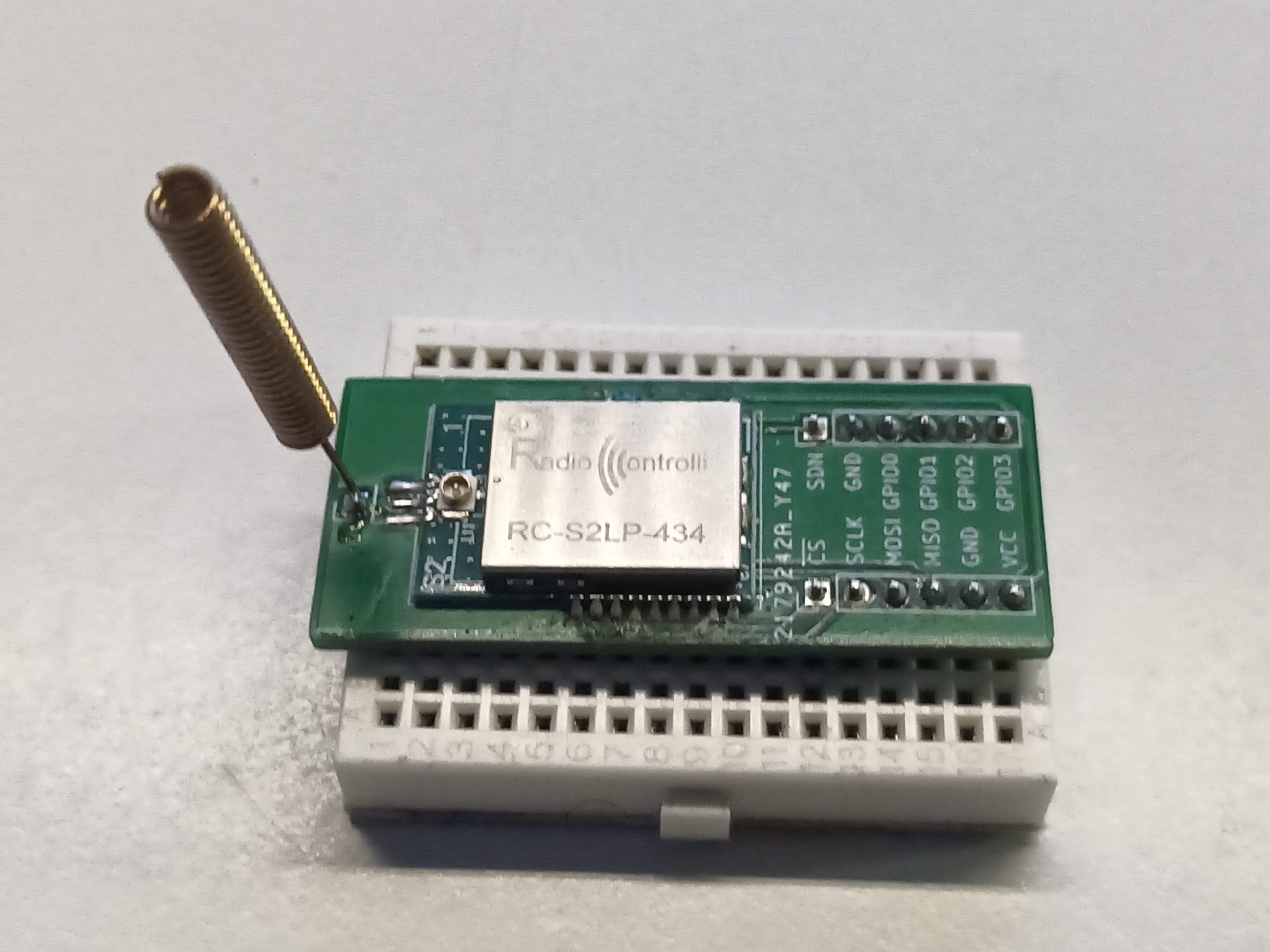
After I got stuck with the Si4332 radio module, where I seemed to get a packet from one module to another, but the content of the packet was wrong, I concluded I had no way to tell whether the problem was on the sending or the receiving end. How to go on with this? Take another module and see what it receives. Another module I have at hand is the S2-LP from ST. (In some early announcement it was called Spirit2, as it is the successor of the Spirit1).
 For this module, I’ve located a MIT-licensed library at GitHub, https://github.com/SteelPh0enix/S2LP_Driver, with a description “low-level and easy-to-port”. That the kind I am looking for. Porting was straight forwards, just some template SPI and GPIO functions to fill, and ready to go. I confirmed the communication with the radio chip was up and running by reading the DEVICE_INFO registers. Everything looks fine.
I have used the S2LP in the past, many years ago. Back then I based a project on ST’s library. This time I wish to avoid it due the non-free license. Back in the day, I learned one thing about this chip: there are two variants: S2-LPQTR and S2-LPCBQTR. The S2-LPQTR works on 413-479 MHz and 826-958 MHz, the S2-LPCBQTR works on 452-527 MHz and 904-1055 MHz. I wrote some code that worked on the development kit, but it didn’t work well on the prototypes. It turned out, the wrong variant of the chip was used in the prototypes.
This time, I am using modules sold by RadioControlli, an Italian radio module company. So, I won’t run into that problem. Another thing to pay attention to is the crystal. The chip supports 24, 25, 26, 48, 50 and 52 MHz crystals. When the 48, 50 or 52 MHz crystal is used, a clock divider has to be enabled. From the datasheets of the module follows they’ve used a 50 MHz crystal. So, that is the value I enter in my code.
Like the previous time, my first test is to transmit something and look at my RTLSDR to see if it is transmitting. And guess what? It is not. That’s a bummer! Looking at the status register, it seems to be stuck at READY state, not entering TX state. Besides that, the oscillator started bit remains 0. So, I looked at the crystal. I configured it for a 25 MHz crystal instead, and the status code reflected an oscillator error. So, for that part, I guess, the 50 MHz is right.
Apart from sending a packet, I’ve also tried just sending an unmodulated carrier, and a PN9 test signal. In these modes, when I give it the TX command, it should remain transmitting until I give it an ABORT command. Nevertheless, the result remains the same, state is READY, Oscillator is off.
Another dead end for the time being.
Edit: After configuring the current charge pump to 140 µA, as the datasheet suggest for the 50 MHz crystal, either 120 or 140 µA, I am no longer stuck in the READY state. And the crystal is on! However, this time I get into an unknown state 0x74. This state is being mentioned on the ST forums with no resolution in sight.
I might have a look at ST’s libraries for the S2LP. Declutter the code for the evaluation boards and see if I can get those to work with my board. From what I recall, three layers of pin remapping to find what pins the code is even using.