While I have been working on the radio modules. I wasn’t in the mood for more coding (or rather, analysing the magic values generated by WDS), so I made a next revision of the radio PMOD modules. Seems I overlooked the PCB thickness in the KiCad Calculator tool, and ended up with the wrong width of the antenna trace. It should have been much thicker. Might explain why my antenna test PCB wasn’t giving sensible values when I tried to test it with my NanoVNA. Well.. we’ll see. Another thing I have added was a SPI Flash. The idea is to place some information about the module on there, such as the type and frequency.
And then I got distracted with some other stuff. I got a bunch of Neoway M590 kits I bought a couple of years ago. These were dirt-cheap those days. Back in 2018 I paid 89 cents. Back in 2018 I assumed it was so cheap as 2G will shut down in a few years, but these days prices went up to about € 1.70 + shipping. Oh well, I might have a look at them before it’s too late. Note that, back then, and now, the kits are cheaper then single modules.
These Neoway M590 modules come with a PCB and some additional components to solder yourself.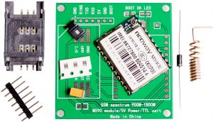 This PCB has been discussed elsewhere on the internet before, but what can I say about it. The designers did everything the Hardware Design Manual tells you not to do.
These, and most other GPRS modules, are designed to run directly of a Lithium Polymer battery. They want a voltage of 3.5V to 4.3V. Thus, it cannot run directly on standard voltages like 3.3V or 5.0V. The Chinese PCB uses a diode to drop a diode drop of 0.7 Volt from a 5.0 Volt supply to get to the 4.3 Volt. This is what the Hardware Design manual tells you not to do:
Never use a diode to make the drop voltage between a higher input and module power. Otherwise, Neoway will not provide warranty for product issues caused by this. In this situation, the diode will obviously decrease the module performances, or result in unexpected restarts, due to the forward voltage of diode will vary greatly in different temperature and current.
There is a another version of the manual stating the voltage range is 3.3V to 4.5V, so it might run on a 3.3 Volt rail anyways. But the power supply line should be able to handle 2 Amp peak current.
Another problem is the fact the module’s TxD and RxD lines are directly connected to the pin header. The module internally works on 2.8 Volts, and when communicating with a 3.3 Volt system, some adjustments are required. I have two revisions of the Hardware Design Manual. While one version recommends placing 200 Ohm resistors in series when interfacing with 3.3 Volt systems, and a proper level shifter when communicating with 5.0 Volt systems, another revision of the manual recommends a shifter for 3.3 Volts as well.
Therefore I am considering designing my own PCB to solder these modules on. One of the questions I’ve got is how I will power it. I am thinking of connecting a LiPo battery to the PCB. That is what the module is designed to run on after all. I will need some custom power anyways as my baseboards are designed to run on 3.3 Volts anyways. Besides, I’ve got plenty of LiPo batteries, as since Big Clive made a video about single use vapes containing rechargeable LiPo batteries, I told my neighbour about it and he gave me a bag of used vapes. All I got to do is rip them open and take the battery.
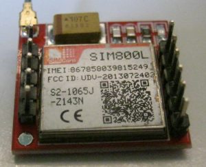 Besides these M590 kits, I also got some SIM800L modules. These are soldered so some breakout PCB. I tried to align the pins using a breadboard, as I usually do when soldering pins to breakout boards. After soldering and taking it out of the breadboard, I discovered the pins were not straight. Apparently its pin rows are not 2.54 mm aligned.
Note that these have similar voltage requirements (3.4V to 4.4V) in the datasheet, but in practice, they turned out to be pickier. I had to add a big capacitor (1000 µF) and supply at least 3.6 Volt otherwise it just won’t run. I suspect adding more and better caps will solve that.