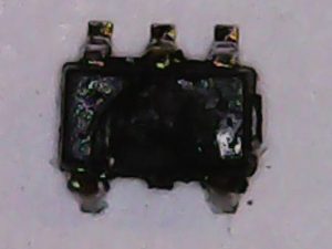
I’ve released the magic smoke. What happened here? These are the remains of an MT2492. This is a step-down converter. This chip was located on a breakout board, taking 12 Volt input, and outputting 5 Volt.

I’ve designed this board last year. Unfortunately, I’ve lost the KiCad files in a hard disk crash. Nevertheless, it’s just the reference design, with a potmeter to set the output voltage. This design also allows other pin compatible chips with different voltages to be used, by adjusting the potmeter.
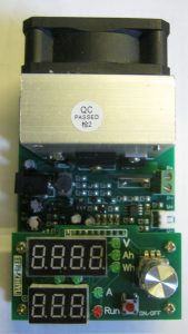
The reason I (tried to) power up this board, is the fact I’m designing another board, where I wish to use this step-down converter. The thing should take 12 Volt input, and output 5 Volt. As this breakout board does. Since I’ve made this board, I’ve obtained an electronic load. I wished to run some tests on the board using that electronic load.
The electronic load also requires a 12 Volt input. At first, I connected my usual 12 Volt supply, incorporated in my work bench, to the breakout board. The board operates as it should, giving a 5 Volt output. So far so good.
Then I connected my 12 Volt supply to the electronic load. I attached the output from the breakout board to the load. I took a 12 Volt supply from my bin of power supplies. Time to test! When I connected the 12 Volt supply from the bin to the breakout board, the magic smoke was released!
 |
|
What went wrong here? Let’s investigate.
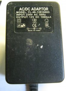
The power supply from the bin was an old fashioned AC/DC power supply. No modern switching power supply. See this YouTube video for some background information. One of the properties of an old fashioned AC/DC power supply is the fact that the output voltage is unregulated, and without load, the output voltage is higher then the rated voltage.
The MT2492 takes input from 4.5 up to 16 Volt. So, even though I was aware the voltage would be higher then 12 Volt, I didn’t think this would be a problem. However, the magic smoke was still released. Now, I measured my output voltage to be 17 Volts. This is the voltage listed as the Absolute Maximum Voltage in the datasheet. Seeing gap between the maximum working voltage 16 volt, and the absolute maximum 17 volts, they’re unconformably close to each other.
The rated input is up to 16 Volts, so I exceeded that. I went up to the absolute maximum, but I didn’t exceed it. So, it shouldn’t have released the magic smoke just yet. I am not entirely sure whether this is what caused the fault. But I have another idea. At the same point, I connected the electronic load. On later inspection, it seems the load was activated on the point I plugged the board in. In theory, this configuration could have caused oscillation.
What could be happening is, a step down converter like this continuously probes the output voltage and adjust the duty cycle to keep the output voltage constant. An electronic load also continuously probes the voltage and adjusts the load to keep the configured current constant. These control loops could interact in such a way they start oscillating. Oscillation could even bring down professional power supplies, and we’re dealing with an el-cheapo Chinese chip.
I could so some more tests to figure this out. Create a splitter cable so I can hook up both a breakout board and the electronic load to the same power supply. But I am a little reluctant do try again because the smell is horrible!
Nevertheless… if the 17 volts input was the problem, I might have to reconsider the chip. The thing is, the power supply I used was rated 12 Volts. Due the old fashioned design, its unloaded voltage is higher. If I put this chip on a board, and say to connect it to a 12 Volt supply, it should accept power from something labelled as a 12 Volt power supply. If the load was the problem, then there should be no problem for my intended application.