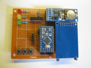
A few years ago, I decided to make a project: A temperature logger, that logs the temperature of a number of DS18B20 sensors and stores them to an SD card. The project consisted of an ATMEL AVR (ATMEGA328P) microcontroller, an RTC, an SD card holder, and of course some temperature sensors.
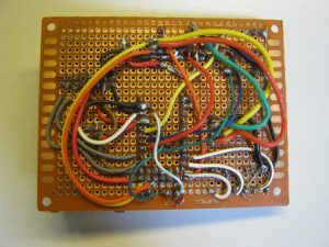
Back then, I didn’t know much about designing PCBs. I googled for PCB manufacturers and I found Eurocircuits. However, the pricing, around 100 euros, was a little too much for just a hobbyist prototype thing. Besides, what software would I need? I was aware of Eagle having a freeware version with some limitations. Nevertheless, the production price made me not investigate this further. I took some prototype boards and wires. The first version I used some headers to plug the modules in.
 |
 |
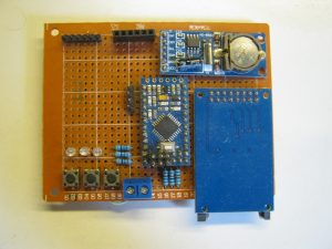
This first prototype appeared to work fine. So I decided to create another one. For this one, I decided not to use the headers, as the modules were flapping in the breeze.
 |
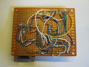 |
However, this one didn’t work. I wasn’t able to figure out what exactly was wrong with it. Did I wire something wrong? Is there a faulty module in there? As I soldered the modules to the board, they’re not easy to replace. Oh well… the advantages and disadvantages of soldering them directly to the board.
It’s pretty time consuming to wire up a board like that, and when it doesn’t work, it’s a huge waste of time. Still looking at the possibilities to create a PCBs, that doesn’t cost be a 50 to 150 euros, I was thinking about etching then myself, like I used to do back at school. However this would require me getting an etching tray. Where to put that thing? I live in a small apartment. Furthermore, what about the fumes? So I discarded that option.
One thing to say, I wasn’t able to debug the microcontroller. The development for the ATMEGA328P was a flash and pray principle. No in circuit debugging. This is one of the reasons why I switched to ARM Cortex-M based microcontrollers, to have some propper in circuit debugging support.
A note, it is actually possible to do in circuit debugging on an ATMEL AVR based MCU. It support a debugging protocol named debugWire. Back then, it would mean I needed a debugger by ATMEL, but now there is an open source implementation that works using an FT232 or CH340 USB TTL Serial adaptor. Have a look at See https://github.com/dcwbrown/dwire-debug
Several years later, I learned about Chinese PCB manufacturers and Open Source PCB software. I’m using KiCAD to draw schematics and PCBs. The first PCB I had drawn I had manufacturer at PCBWay. 10 PCBs for 5 American Dollars. That’s much cheaper then the 150 Euros Eurocircuits would make me pay for that. At a later time, I let some PCBs be manufacturer at JLCPCB. They’re a discount on the first 10 PCBs in an order. Then you pay 3 American Dollars for the first 10, and if you upload a seccond design, it’s 5 Dollars for another 10. And there are many more Chinese PCB manufacturers.
One Thing about JLCPCB, they also have a electronic components distributors. Much like Farnell and RS here in Europe, but based in China. It’s called LCSC. For ordering electronic components, it’s worth having a look at them. For example, an STM32F103C8T6, let’s say, for 100 pieces, at RS, € 3,92/piece. at Farnell € 3,93/piece, at LCSC $1,13/piece. That’s some savings, aint’ it?
That’s it for now. I’ll write some more about the PCBs I’ve designed in the future. I should also continue on my PSoC4 project, so I can’t promise yet what my next post will be about.