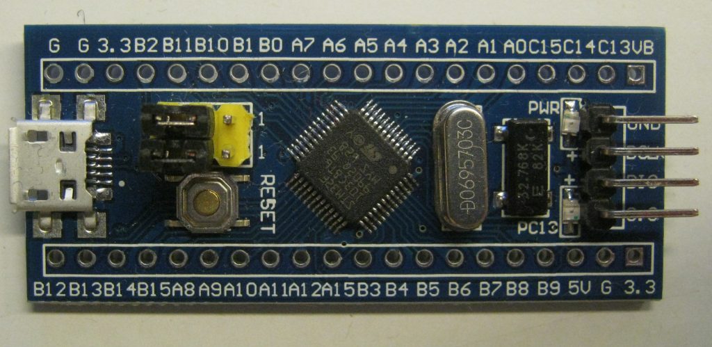
Blue Pill
| Known in the community as | Blue Pill |
| Search term on eBay/AliExpress | STM32F103C8T6 Minimum System Development Board |
Introduction
The Blue Pill is a popular board sold on eBay, AliExpress and the likes. It consists of an STM32F103C8T6 microcontroller. There are some variants of this board.
Regarding the microcontroller, some recent board may supply a microcontroller from an alternative supplier, such as the CS32F103C8T6. Furthermore, lately there are signs of fake STM32 chips. These are chips marked as being an STM part, but are produced by a different manufacturer. These might be relabelled CS32 or some other part. See https://www.richis-lab.de/STM32_01.htm for a peek inside the faked chips, and have a look at my comparison of *32F103 parts.
As far as I have been able to tell, this design originated from www.vcc-gnd.com. vcc-gnd sells board not only with the STM32F103, but also with other STM32 microcontrollers such as the STM32F030, STM32F051, and the STM32F072. Even though it is known Blue Pills with other microcontrollers are known to be sold, I think it is rather unlikely to find them in the wild on eBay/AliExpress. So, unless you’re explicitly looking for a different board, it’s safe to assume a Blue Pill got an STM32F103 (or equivalent) microcontroller.
Board Features
Micro USB connector
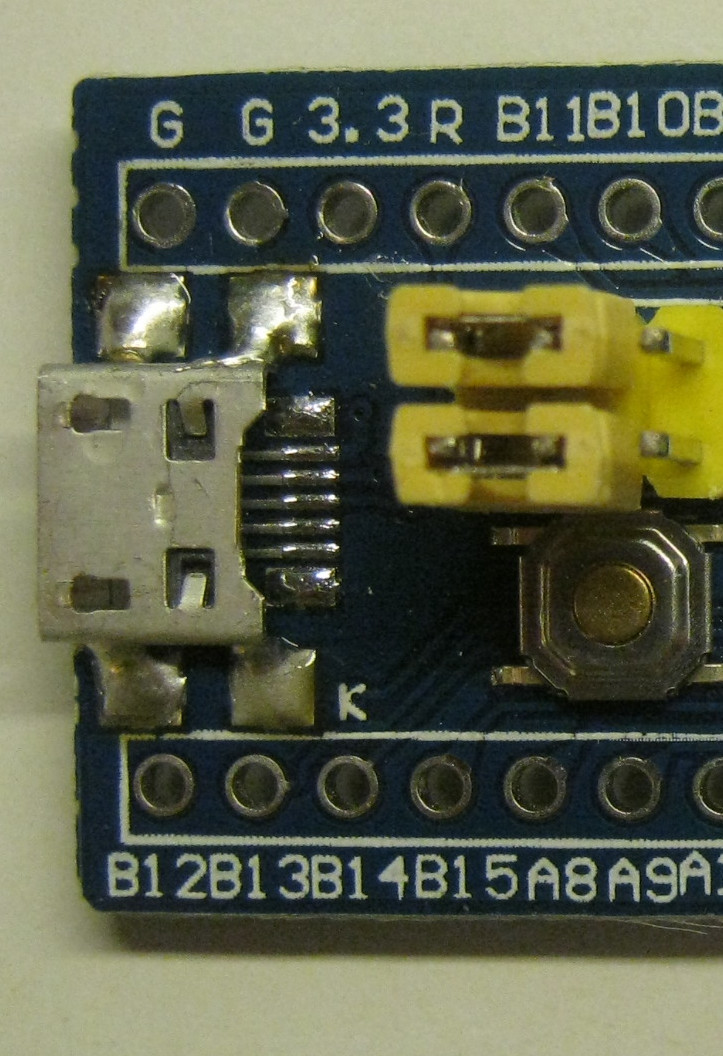 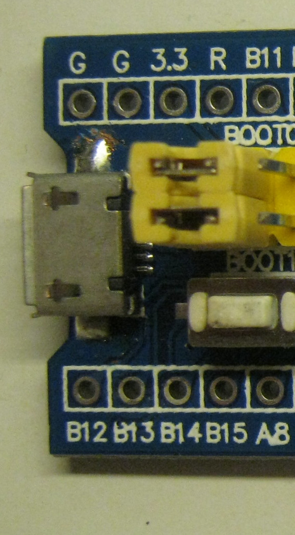 |
The Micro USB connection can to used for both powering the board and USB communication. There are variants where the USB has two enforcements going through the board, and variants where there is only a single enforcement on one side. For either version, you might want to apply some solder to the enforcements to make them effective. Nevertheless, I’d recommend getting the version with the through-board enforcements. |
| The microcontroller features a USB Device peripheral. The USB Pull-up resistor is hard wired. This is resistor R10. For many years, the boards came with the wrong value for R10. A common bad value is 10K (103). The correct value should be 1K5 (152). If your board comes with the wrong value, you should replace the resistor, otherwise USB might not function correctly. | |
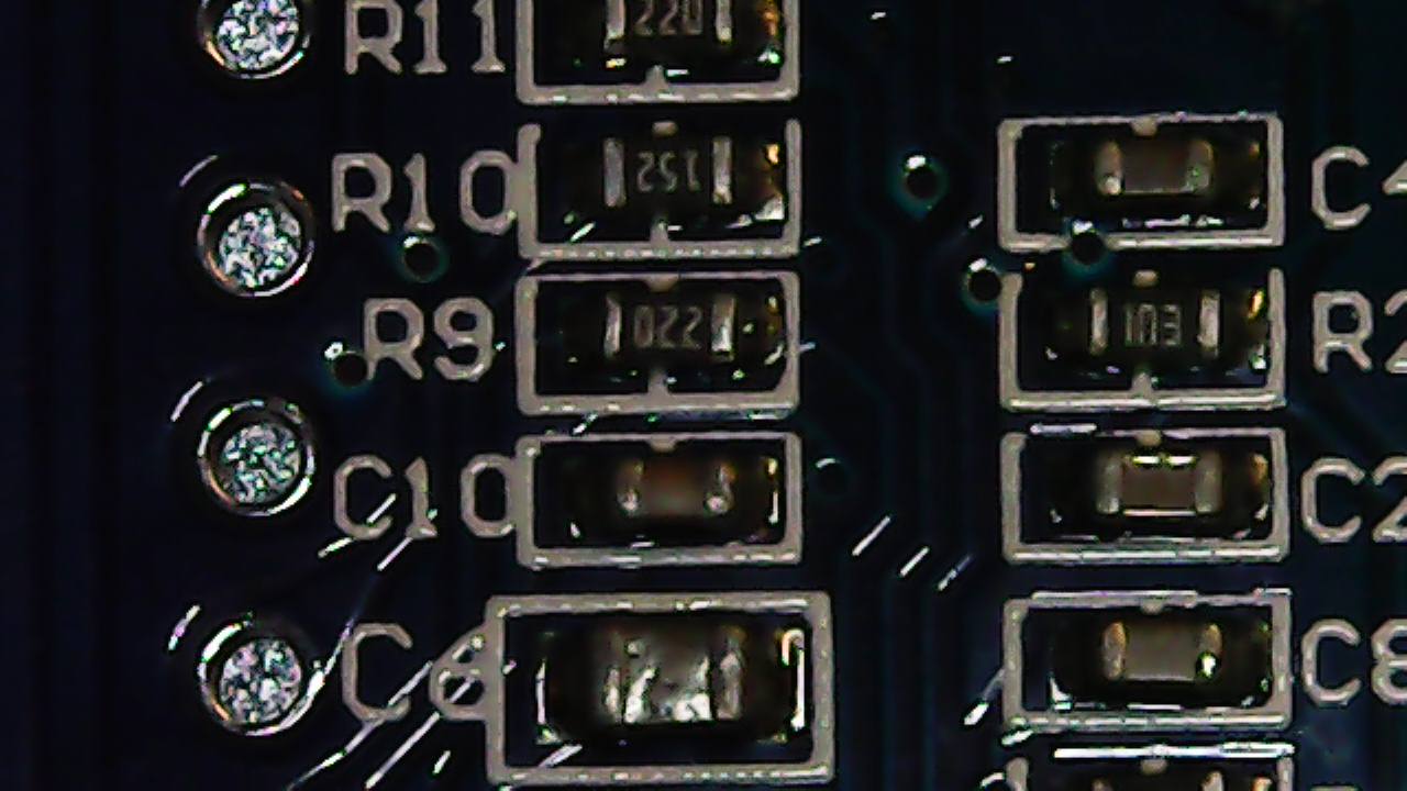 R10 has the correct value “152” |
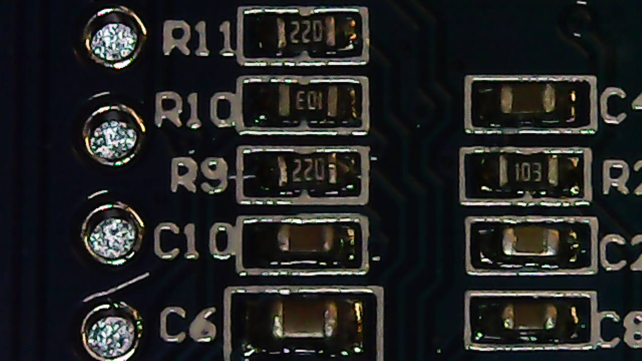 R10 has the wrong value “103” |
The board has an on board regulator that turns the 5 Volts from USB to 3.3 Volts for the microcontroller.
Please be aware the USB pins are also connected to the pins (PA11,PA12).
Boot selector jumpers
The board comes with two jumpers, which allow to pull up or down the BOOT0/BOOT1 pins. These pins select how the microcontroller boots. In the default configuration (both pins to ground) the microcontroller boots the firmware in flash. Other modes include boot from RAM, and boot from BOOTROM, which has an internal UART bootloader that allows uploading firmware over UART.
Reset button
A button to reset the microcontroller
Crystals
The board comes with an 8 MHz high frequency oscillator, and a 32.768 KHz low frequency oscillator.
LEDS
The board comes with a power LED, and a user LED hooked up to PC13, (TODO: check polarity)
SWD connector
The board comes with a right angle header exposing the SWD pins. The pin order is 3.3V, SWDIO, SWCLK, GND.